|
|
|
Kto jest w sklepie?
Sklep przegląda 6043 gości |
|
Kategorie
|
|
Informacje
|
|
Polecamy
|
|
|
 |
|
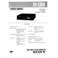
- GENERAL
- Location and Function of Controls
- Monitor Adjustment and Preparation
- Color Adjustment and Correction During Editing
- DISASSEMBLY
- Removal of Cabinet, Front Panel
- Removal of FT - 38 Board
- Removal of FT - 39 Board
- Opening of CA - 16 Board
- Opening of WF - 1 Board
- DIAGRAMS
- Circuit Boards Location
- Color Correct Block Diagram
- Back Color Signal Generator Block Diagram
- Audio/Power Block Diagram
- PRINTED WIRING BOARDS AND SCHEMATIC DIAGRAMS
- Frame Schematic Diagram
- Printed Wiring Boards and Schematic Diagrams
- FT - 39, FT - 38, JK - 44, AM - 13, IS - 5 and MJ - 22 Boards
- AC - 44, PT - 68, PT - 70 and PW - 61 Boards
- Semiconductors
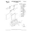
- EXPLODED VIEWS
- Cabinet, Front Panel Assemblies
- Main Board Assembly
- ELECTRICAL PARTS LIST
- ELECTRICAL ADJUSTMENT
- Adjustment of Power Supply Block
- - 5V, +9V Adjustment
- +5V, +6V and - 6V Confirmation
- Adjustment of Internal SYNC. Signal and Timing Generator
- INT SYNC fsc Adjustment
- INT SYNC Burst Level Confirmation
- INT SYNC Level Confirmation
- H AFC Adjustment
- H Front Blanking Adjustment
- H Back Blanking Adjustment
- V Blanking Adjustment
- Adjustment of Composite Video Signal System
- Y - SEP Level Adjustment
- C - SEP Frequency Characteristic Adjustment
- C - SEP Level Adjustment
- Y - C SEP Frequency Characteristic Adjustment
- Composite Y Level and Chroma Level Adjustment
- Adjustment of Y Main Signal System, Negative/Positive Inverter and Y - γ Circuit
- Pilot Signal Level Adjustment
- Negative AGC Adjustment
- Y - γ Center Adjustment
- Positive AGC Adjustment
- Y - γ LOW and Y - γ HIGH Adjustment
- C - γ Adjustment
- Y Level and SYNC Level Adjustment
- Adjustment of Chroma Main Signal System and Burst Signal System
- COLOR VR Center Adjustment
- Chroma Lever Adjustment
- Burst Phase Adjustment (Using the Vectorscope)
- Burst Level Adjustment
- CNR Adjustment
- Adjustment of Fader/Wipe Back Color System
- Back Color Bar Adjustment
- Fader/Wipe Back Color Y Level and Back Color Y Level Adjustment
- Fader White Level Adjustment
- fsc Adjustment
- ACC Peak Adjustment
- ACC Adjustment
- Fader/Wipe Back Color Chroma Level/Phase Adjustment (Using the Vectorscope)
- Fader/Wipe Back Color Chroma Level/Phase Adjustment (Using the Oscilloscope)
- Back Color INT Mode Phase Adjustment
- Adjustment of Color Correct System
- Color Correct Carrier Balance Adjustment
- Chroma Limiter Adjustment
- Color Correct Phase Adjustment (Using the Vectorscope)
- Color Correct Position Adjustment (Using the Monitor TV)
- Color Correct Level Adjustment
- Adjustment of Wipe System
- H RAMP Level Adjustment
- V RAMP Level Adjustment
- H RAMP, V RAMP DC Clamp Level Adjustment
- Diamond Pattern Center Adjustment
- Round Wipe Pattern Roundness Adjustment
- Round Wipe Pattern Position Adjustment
- Round Wipe Pattern Size Adjustment
- Adjustment of VIDEO ART and Split Screen System
- VIDEO ART REVERSE Level Adjustment
- VIDEO ART VR Center Adjustment
- Split Screen Adjustment
- Adjustment of Audio System
- Audio Output Level Adjustment
- Parts Location Diagram Relevant to the Adjustment
Dla tego produktu nie napisano jeszcze recenzji!
 ;
Dokładna dokumentacja, pomogła w szybkiej naprawie telewizora. Dziękuję!
 ;
jedyne do czego mogę mieć zastrzeżenie to jakość zdjęć zawartych w przesłanej instrukcji serwisowej ponieważ są fatalnej jakości, praktycznie nieczytelne. tak poza tym jestem zadowolony to jest to czego szukałem.
;
Wszystko w porządku.
Instrukcja czytelna i kompletna.
Dziękuję.
all right!
thank you.
;
Bardzo dobra instrukcja. Zawiera wszystko co potrzeba, polecam!
;
Instrukcja jest OK. Schematy czytelne, opisane niektóre procedury.
|
|
|
> |
|