|
|
|
Kto jest w sklepie?
Sklep przegląda 5836 gości |
|
Kategorie
|
|
Informacje
|
|
Polecamy
|
|
|
 |
|
|
Dla tego produktu nie napisano jeszcze recenzji!
 ;
jedyne do czego mogę mieć zastrzeżenie to jakość zdjęć zawartych w przesłanej instrukcji serwisowej ponieważ są fatalnej jakości, praktycznie nieczytelne. tak poza tym jestem zadowolony to jest to czego szukałem.
 ;
Wszystko w porządku.
Instrukcja czytelna i kompletna.
Dziękuję.
all right!
thank you.
;
Bardzo dobra instrukcja. Zawiera wszystko co potrzeba, polecam!
;
Instrukcja jest OK. Schematy czytelne, opisane niektóre procedury.
;
Instrukcja bardzo czytelna. zawiera co potrzeba. Polecam
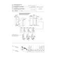
Record/Playback Head Azimuth Adjustment DECK A Procedure: 1. Forward Playback Mode
test tape P-4-A100 (10 kHz, �10 dB) 47 k� set
DECK B
Tape Speed Adjustment Procedure: �Forward Playback Mode�
test tape WS-48B (3 kHz, 0 dB)
DECK A
DECK B
level meter
frequency counter 47 k� set
+ �
+ �
LINE OUT
LINE OUT
2. Turn the adjustment screw for the maximum output levels. If these levels do not match, turn the adjustment screw until both of output levels match together within 1 dB.
L-CH peak
output within level 1 dB
within 1 dB
(High speed adjustment) 1. Set to test mode. (Refer to page 10.) 2. Set to FWD playback mode. 3. Twice pressing the HIGH/NORMAL switch. 4. Adjust RV316 (DECK A), RV416 (DECK B) so that the frequency counter reading becomes 5,980 ± 20 Hz. 5. Release test mode after adjustment is completed. (Normal speed adjustment) 1. Set to FWD playback mode. 2. Adjust RV317 (DECK A), RV417 (DECK B) so that the frequency counter reading becomes 3,000 ± 10 Hz. (Pitch control adjustment) (DECK A) (TC-WE525 only) 1. Push the PITCH CONTROL switch. 2. Set RV986 (PITCH CONTROL knob) to mechanical center. 3. Set to FWD playback mode. 4. Adjust RV318 so that the frequency counter reading becomes 2,990 ± 10 Hz. Frequency difference between the beginning and the end of the tape should be within ± 3%. Frequency difference between the deck A and deck B the beginning of the tape should be within ± 1.5%. Adjustment Location: MAIN board (See page 13.)
screw position
R-CH peak L-CH peak R-CH peak
screw position
3. Playback Mode
test tape P-4-A100 (10 kHz, �10 dB)
L-CH
47 k�
oscilloscope
set
V
+ �
H + �
R-CH
47 k�
Playback Level Adjustment Procedure: �Forward Playback Mode�
test tape P-4-L300 (315 Hz, 0 dB) set
DECK A
DECK B
LINE OUT Screen Pattern
level meter 47 k�
+ �
In phase 45� good
90�
135� 180� wrong
LINE OUT
4. Change the reverse playback mode and repeat the steps 1 to 3. 5. After the adjustment, lock the adjustment screws with suitable locking compound. Adjustment Location: �record/playback head�
Adjust DECK A : RV111 (L-CH), RV211 (R-CH) and DECK B : RV121 (L-CH), RV221 (R-CH) so the level meter reading becomes the adjustment limits below. Adjustment Value: LINE OUT level : �7.7 ± 0.5 dB (0.301 to 0.338 V) Level difference between channels : within 0.5 dB Confirm that the LINE OUT level does not change in playback mode while changing the mode from playback to stop several times. Adjustment Location: MAIN board (See page 13.)
forward side
reverse side
adjustment screws
� 11 �
|
|
|
> |
|