|
|
|
Kto jest w sklepie?
Sklep przegląda 6043 gości |
|
Kategorie
|
|
Informacje
|
|
Polecamy
|
|
|
 |
|
|
Dla tego produktu nie napisano jeszcze recenzji!
 ;
jedyne do czego mogę mieć zastrzeżenie to jakość zdjęć zawartych w przesłanej instrukcji serwisowej ponieważ są fatalnej jakości, praktycznie nieczytelne. tak poza tym jestem zadowolony to jest to czego szukałem.
 ;
Wszystko w porządku.
Instrukcja czytelna i kompletna.
Dziękuję.
all right!
thank you.
;
Bardzo dobra instrukcja. Zawiera wszystko co potrzeba, polecam!
;
Instrukcja jest OK. Schematy czytelne, opisane niektóre procedury.
;
Instrukcja bardzo czytelna. zawiera co potrzeba. Polecam
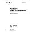
Ver 1.5 2001. 01
SECTION 5 ELECTRICAL ADJUSTMENTS
PRECAUTIONS FOR ADJUSTMENT
1) Perform all adjustments in the order given in the test mode. After adjusting, exit the test mode. 2) Use the following tools and measuring instruments. � Test CD TDYS-1 (Part No. : 4-963-646-01) � SONY MO disc available on the market � Laser power meter LPM-8001 (Part No. : J-2501-046-A) � Oscilloscope (Frequency band above 40 MHz. Perform the calibration of probe first before measuring.) � Digital voltmeter 3) Unless specified othewise, supply DC 3V from the DC IN 3V jack. 4) Swtich, knob positions HOLD switch .............. OFF AVLS switch ................ NORM
MO TRAVERSE ADJUSTMENT
Connection :
oscilloscope MAIN board TP5980 (TE) AP5430 (VC)
Adjustment Method : 1. Set the servo mode of the test mode (Mode : 000). 2. Press the ( key, and set the MO test adjustment mode (Mode : 030) using the VOLUME + or � key. 3. Press the = or + key and move the optical pick-up to the center circumference. 4. Insert any MO disk available on the market. 5. When the ( key is pressed, the MO read FE balance adjustment mode (Mode : 032) will be set after MO focus search adjustment mode (Mode : 031). 6. Press the P key to perform automatic adjustment, and check that the traverse waveform is symmetrical at the top and bottom. 7. Slide the REC key and set the MO write FE balance adjust ment mode (Mode : 034). 8. Press the P key to perform automatic adjustment, and check that the traverse waveform is symmetrical at the top and bottom.
LASER POWER CHECK
Connection :
laser power meter
Optical pick-up objective lens
(Traverse waveform)
digital voltmeter MAIN board AP5117 (VCC) AP574 (LDI0)
A 0V B Specification : A = B, C = 1.0 Vp-p > C
Adjustment Method : 1. Set the servo mode of the test mode (Mode : 000). 2. Press the ( key, and set the laser power adjustment mode (Mode : 020) using the VOLUME + or � key. 3. Press the = key and move the optical pick-up to the inner most circumference. 4. Open the cover and set the laser power meter on the objective lens of the optical pick-up. 5. Press the ( key, and set the laser CD/MO read adjustment mode (Mode : 021). 6. Check that the laser power meter reading is 0.85 ± 0.085 mW. 7. Check that the voltage between AP5117 (VCC) and AP574 (LDI0) at this time is below 44 mV. 8. Press the ( key, and set the laser MO write adjustment mode (Mode : 022). 9. Check that the laser power meter reading is 6.8 ± 0.68 mW. 10. Press the P key to finalize the adjustment data. 11. Check that the voltage between AP5117 (VCC) and AP574 (LDI0) at this time is below 80 mV. 12. Press the p key. 13. Exit the test mode. Adjustment Location : See page 19.
9. Check that the traverse level at this time is above 1.0 Vp-p. 10. Press the p key. 11. Exit the test mode.
Note) Using a recorded disk in this adjustment will erase the data.
Adjustment Location : See page 19.
� 17 �
|
|
|
> |
|