|
|
|
Kto jest w sklepie?
Sklep przegląda 5970 gości |
|
Kategorie
|
|
Informacje
|
|
Polecamy
|
|
|
 |
|
|
Dla tego produktu nie napisano jeszcze recenzji!
 ;
Wszystko w porządku.
Instrukcja czytelna i kompletna.
Dziękuję.
all right!
thank you.
;
Bardzo dobra instrukcja. Zawiera wszystko co potrzeba, polecam!
 ;
Instrukcja jest OK. Schematy czytelne, opisane niektóre procedury.
;
Instrukcja bardzo czytelna. zawiera co potrzeba. Polecam
;
...instrukcja serwisowa w pełni czytelna i kompletna. Dziękuję!
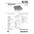
SECTION 4 TEST MODE
Outline � In this set, overall adjustment mode is made available by entering test mode to perform automatic adjustment of CD and MO. In the overall adjustment mode, the disc is determined whether it is CD or MO and adjustments are performed in sequence. If a fault is found, the location of the fault is displayed. Also, in servo mode, each adjustment can be automatically made. � Operation in the test mode is performed with the remote commander. A key having no particular description in the text, indicates a remote commander key. Setting the Test Mode To enter the test mode, two methods are available : 1. Entering method with key input. Turn on the HOLD switch on the set. While pressing the p key on the set, press the following remote commander keys in the following order : �/+ n �/+ n = n = n �/+ n = n �/+ n = n P n P 2. Entering method by shorting the test point Solder bridge the test point TAP805 (TEST) on the MAIN board (connect IC801 pin #£ to GND), and turn on the power. � MAIN BOARD (Conductor side) � Configuration of Test Mode The test mode has the configuration given below.
VOL + key
p key
Overall �/ + key adjustment mode (044 Auto?)
p key
(044 Start?)
p key
VOL � key
p key
Adjustment �/ + key mode (044 Manu?)
Servo mode 000 VOL +/� keys Audio mode 100 VOL +/� keys Power mode 300
is set
Display when test mode
Displays of the LCD on the remote commander are shown in parenthesis.
Servo Mode � Set the test mode, press the VOL � key and use the �/+ key to set the servo mode. � When the servo mode is set, use the +/� key and the = key on the set to move the optical pick-up to the outer circumference and to the inner circumference respectively. � When entering another mode, refer to the configuration of test mode. 1. Structure of Servo Mode
Servo mode 000
p key �/ + key
Offset adjustment 010
+/� keys
�/ + key
Test mode
011 to 014
(
Short : Test mode Open : Normal mode
)
p key
p key
*1 �/ + key
Releasing the Test Mode A test mode releasing method varies depending on the test mode setting method. 1. When test mode was entered with key input, turn off the power. 2. When test mode was entered by shorting the test point, turn off the power and open the solder bridge of TAP805 (TEST MODE) on the MAIN board. Operation of Setting on Test Mode When the test mode is set, the LCD displays the following :
SHUF 1
Laser power adjustment 020
�/ + key
VOL
p key
021 to 024 *1 �/ + key
2
3
(See page 7.)
100 V1. 000
LCD on remote commander
ROM version display
� The cycle - the above ROM version display n All lit n All off - is repeated. � When the PLAYMODE key is pressed and hold down, the display at that time is held so that display can be checked.
*1 Repeatedly press �/ + key to change the mode. (Refer to the following list for a description of each mode.)
�6�
VOL +/� keys
|
|
|
> |
|