|
|
|
Kto jest w sklepie?
Sklep przegląda 5896 gości |
|
Kategorie
|
|
Informacje
|
|
Polecamy
|
|
|
 |
|
|
Dla tego produktu nie napisano jeszcze recenzji!
 ;
Dokładna dokumentacja, pomogła w szybkiej naprawie telewizora. Dziękuję!
 ;
jedyne do czego mogę mieć zastrzeżenie to jakość zdjęć zawartych w przesłanej instrukcji serwisowej ponieważ są fatalnej jakości, praktycznie nieczytelne. tak poza tym jestem zadowolony to jest to czego szukałem.
;
Wszystko w porządku.
Instrukcja czytelna i kompletna.
Dziękuję.
all right!
thank you.
;
Bardzo dobra instrukcja. Zawiera wszystko co potrzeba, polecam!
;
Instrukcja jest OK. Schematy czytelne, opisane niektóre procedury.
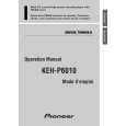
1-1-4. Discharge of flashlight power supply The capacitor which is used as the power supply of flashlight is charged with 200 V to 300 V voltage. Discharge this voltage before starting adjustment in order to protect service engineers from electric shock during adjustment . Discharge procedure 1. Turn OFF the flash switch by pressing the switch S705 on the PK-43 board which turns OFF the flash charging lamp. 2. Fabricate the discharging jig as shown in Fig. 5-1-6 locally by yourself. Connect the discharging jig to the positive (+) and negative (-) terminal of the flash voltage charge capacitor. Allow ten seconds to discharge the voltage.
Capacitor
R
Flash circuit board
R : 1k� 1W (Part code No. 1-215-869-11)
Fig. 5-1-6
1-1-5.
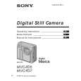
Adjustment remote commander (RM-95 upgraded) To perform adjustment, the adjustment data stored in the non-volatile memory must be rewritten using the adjustment remote commander (RM-95 upgraded). The adjustment remote commander uses the remote commander signal line (LANC) to interactively communicate with the merchandise. The page, address and up/down command data are sent from the adjustment remote commander to the merchandise. In return, the page, address and data are sent to the adjustment remote commander from the merchandise. 1. Using the adjustment remote commander 1) Connect the adjustment remote commander to the LANC terminal (CPC jig). 2) Set the NOR-ADJ (or HOLD) switch of the adjustment remote commander to the �ADJ� (or ON) (service) position. If the adjustment remote commander is correctly connected, the adjustment remote commander�s LED will show the display as shown in Fig. 5-1-7. Bit value discrimination It is necessary to discriminate between the bit values with the data displayed on the adjustment remote commander for all following items. Identify whether the bit value is �1� or �0� with the use of the following diagram.
Display on the adjustment remote commander
Display on the adjustment remote commander 0 1 2 3 4 5 6 A 7 8 9 A (A) B (b) C (C) D (d) E (E) F (F) bit3 or bit7 0 0 0 0 0 0 0 0 1 1 1 1 1 1 1 1
Bit values bit2 or bit6 0 0 0 0 1 1 1 1 0 0 0 0 1 1 1 1 bit1 or bit5 0 0 1 1 0 0 1 1 0 0 1 1 0 0 1 1 bit0 or bit4 0 1 0 1 0 1 0 1 0 1 0 1 0 1 0 1
3)
B
(Example) If �8E� is displayed on the adjustment remote commander, the bit values for bit7 to bit4 are shown in the A column, and the bit values for bit3 to bit0 are shown in the B column.
Address Page bit3 to bit0 discrimination bit7 to bit4 discrimination
Fig. 5-1-7
5-4
|
|
|
> |
|